
Building a robot is hard when a joint wobbles, a gripper flexes, or a sensor mount is off by 0.05mm. These small errors kill precision. High-quality CNC Machining for Robotics addresses these problems by providing the strength and precision needed for complex movements.
CNC machining creates essential robotic parts like joints, housings, and structural frames. It uses materials like aluminum and titanium to provide the perfect balance of weight and strength. This process ensures parts have the tight tolerances required for smooth, accurate, and repeatable robotic motion.
Finding the right parts can be the difference between a successful project and a costly failure.
Continue reading.
What robotic parts are manufactured using CNC machining?
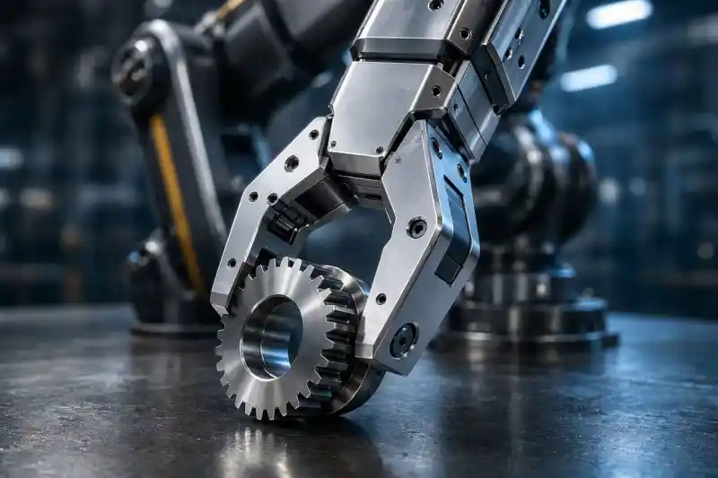
Low-quality parts lead to wobbly joints and failed sensors. This ruins the precision of your entire robotic system. CNC machining delivers the exact dimensions needed for high-performance components.
Robotic parts made by CNC machining include joints like harmonic drive housings, end effectors like grippers, and sensor mounts for cameras. It also produces structural frames and bases. These parts require high concentricity and rigidity to ensure the robot moves smoothly and carries its load safely.
In my experience at Ranglink, I always ask customers where a part will be installed. A rotating joint needs different logic than a fixed bracket. For example, harmonic drive¹ parts are the “crown jewel” of robotic CNC. We once made output flanges for harmonic reducers using 4140 steel. We held an internal hole tolerance of ±0.005mm. If these parts are not perfect, the robot joint will shake or have gaps.
End effectors² are another big category. Every extra gram at the end of an arm reduces the payload. We often use 7075 aluminum for grippers because it is light but strong. We recently made a finger for a collaborative robot³. It had a wall thickness of only 1.5mm but could hold a 5kg workpiece. This balance of weight and strength is only possible with precision CNC work.
| Part Category | Common Components | Key Requirements |
|---|---|---|
| Joints | Harmonic drive housings, RV reducer flanges | High concentricity⁴, tight tolerances |
| End Effectors | Gripper fingers, vacuum tool brackets | Lightweight, high rigidity |
| Sensor Mounts | Camera bases, force sensor plates | Flatness, precise hole placement |
| Structures | Arm links, base flanges, chassis⁵ | Strength, vibration damping |
What are the best materials for custom robotic parts?
Choosing the wrong material can make your robot too heavy or too weak. This leads to slow performance or mechanical breakages. Using the right metal or plastic ensures the robot lasts a long time.
The best materials for robotic parts are Aluminum (6061 and 7075) for a balance of weight and cost. Titanium is used for high-end medical robots. Steel alloys like 4140 are best for heavy-duty gears. Engineering plastics like PEEK or POM provide insulation and low friction.
Aluminum is the main choice for most of our projects. I usually suggest 6061⁶ for frames because it is easy to machine and cheap. However, for high-stress parts like joint shells, I recommend 7075⁷. It is as strong as steel but much lighter. Titanium⁸ is great but very hard to work with. It wears down tools fast. If you do not absolutely need titanium, I often suggest 7075 aluminum to save money and time.
Steel is still necessary for heavy robots. Aluminum cannot handle the wear on a reducer’s crank shaft. We use 4140 steel⁹ for these parts. For lighter tasks or insulation, we use plastics. POM¹⁰ is great for gears because it is quiet. PEEK is perfect for high-heat areas. At Ranglink, we adjust our tools for plastics to avoid melting the material, ensuring a clean finish.
| Material | Key Property | Best Use Case |
|---|---|---|
| Aluminum 6061 | Versatile, Low cost | Brackets, structural frames |
| Aluminum 7075 | High strength-to-weight | Grippers, high-stress joints |
| Titanium Ti-6Al-4V | Biocompatible, Extreme strength | Medical robots, aerospace drones |
| Alloy Steel 4140 | Wear resistance, Toughness | Gears, shafts, heavy-duty joints |
| PEEK / POM | Low friction, Lightweight | Gears, insulators, sliding parts |
Why are tight tolerances critical in robotics CNC machining?
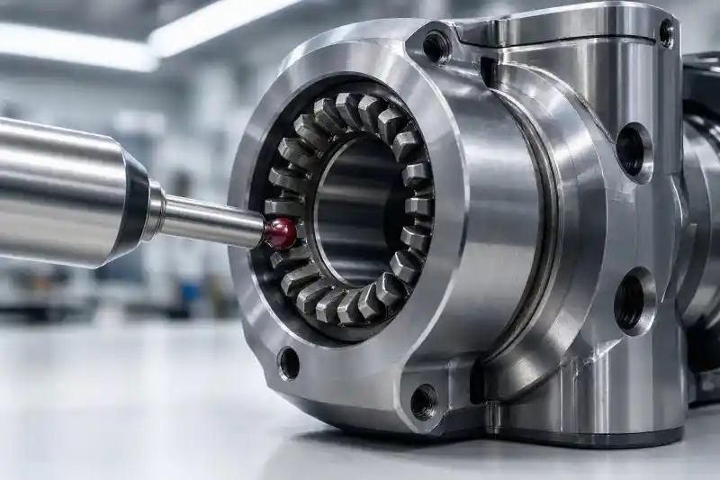
Small errors in individual parts add up quickly in a robotic arm. A tiny gap in one joint becomes a huge wobble at the hand. Tight tolerances prevent these errors from ruining your robot’s accuracy.
Tight tolerances are critical because robotic errors are “serial.” Small mistakes in each joint accumulate, leading to poor positioning at the end of the arm. Precise tolerances ensure zero backlash, reduce vibration, and allow for smooth movement during high-speed tasks.
A six-axis robot has many joints. If every part has a 0.02mm error, the end of the robot might be off by 0.1mm or more. This is why we aim for tolerances within ±0.01mm. For harmonic drives, we often go down to ±0.005mm. We use CMM¹¹ machines to check every tooth and hole. This ensures there is no “backlash¹²” or “play” when the robot changes direction.
Vibration¹³ is another silent killer. If a part is too thin or the fit is loose, the robot will shake at high speeds. This ruins the surface finish of whatever the robot is making. When we machine thin-wall parts at Ranglink, we use special jigs to keep them stiff. We also control surface roughness¹⁴ (Ra). A sliding surface needs a Ra of 0.4 to 0.8 to stay lubricated and move without sticking.
| Feature | Typical Tolerance | Impact on Performance |
|---|---|---|
| Joint Fits | ±0.005mm to ±0.01mm | Eliminates backlash and “jumping” |
| Bearing Seats | ±0.01mm | Reduces friction and heat |
| Mounting Holes | ±0.02mm | Ensures parts align during assembly |
| Surface Finish | Ra 0.4 – 1.6 μm | Affects wear and seal life |
How does CNC machining accelerate rapid prototyping for robotics?
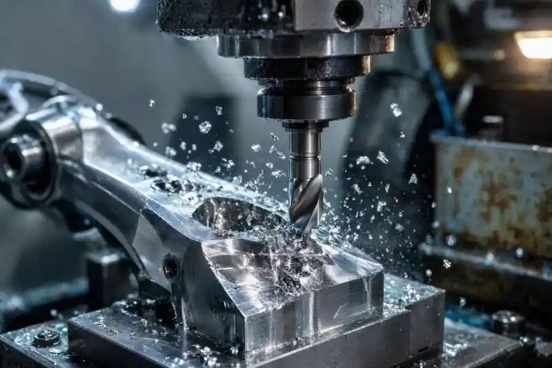
Waiting months for parts kills your development schedule. If you cannot test your design quickly, your competitors will beat you to market. CNC machining turns your digital files into real parts in days.
CNC machining accelerates prototyping by delivering functional metal parts in 3 to 7 days. Unlike 3D printing, CNC parts have the same strength as mass-produced parts. This allows engineers to test the robot’s real-world performance, speed, and durability immediately.
The biggest pain for robot developers is the speed of change. You might only have a few months to finish a prototype¹⁵. Waiting for injection molds takes too long. I have seen clients lose months waiting for tools. With CNC, we can take a CAD file and have a part ready in a week. This allows you to put the part on the robot and start testing right away.
CNC is also better than 3D printing¹⁶ for testing. A printed part does not have the same strength as a solid block of aluminum. If you want to test how a robot arm reacts to a heavy load, you need a CNC part. Also, during the prototype phase, we provide DFM (Design for Manufacturing)¹⁷ feedback. We might find a wall that is too thin or a corner that is too sharp. Fixing these things now saves a lot of money later.
| Factor | CNC Machining | Injection Molding¹⁸ | 3D Printing (Metal) |
|---|---|---|---|
| Lead Time | 3 – 7 Days | 6 – 10 Weeks | 2 – 5 Days |
| Material Strength | High (Real Metal) | High | Moderate (Porous) |
| Cost (1-10 pcs) | Moderate | Very High (Tooling) | High |
| Scalability | Easy transition | Best for millions | Limited |
Conclusion
Precision CNC machining is the backbone of reliable robotics. By choosing the right materials and maintaining tight tolerances, you ensure your robot performs with speed and accuracy.
Ready to start your next project?
Whether you need high-precision batch production or expert advice on the best machining path, I am here to help.
Contact me today for a fast quote:
Email: info@ranglink.com
WhatsApp: Message us on WhatsApp
- Technical explanation of harmonic drives or strain wave gearing systems.
- Overview of robotic end effectors, grippers, and tooling.
- Information on collaborative robots designed to work alongside humans.
- Definition of concentricity in geometric measurement and design.
- Explanation of structural frames and chassis in mechanical engineering.
- Properties and industrial applications of 6061 aluminum.
- Technical specifications of high-strength 7075 aluminum alloy.
- Information on titanium’s physical properties and machining behavior.
- Details on 4140 chromoly steel used for high-stress applications.
- Properties and uses of Polyoxymethylene (POM) engineering plastic.
- Overview of Coordinate Measuring Machines (CMM) for precision inspection.
- Engineering definition of backlash and play in mechanical mechanisms.
- The science of mechanical vibration and its impact on structures.
- Engineering standards and measurements for surface finish and roughness.
- Definition and stages of product prototyping in engineering.
- Guide to 3D printing and additive manufacturing technologies.
- Principles of Design for Manufacturability (DFM) in product engineering.
- Details on the injection molding process for mass production.