
Does your latest mechanical design keep failing at the prototype stage due to warping or ugly surface marks? These common CNC defects often stem from hidden stresses and rigid setups.
To prevent CNC machining defects like warping and tool marks, you must balance internal material stresses through symmetrical material removal, use sharp tools with correct feed rates to stop burr formation, and ensure maximum setup rigidity to eliminate vibration-induced chatter and surface irregularities.
Many engineers feel frustrated when a perfect 3D model¹ turns into a “potato chip” or a rough part once it leaves the machine. I have spent 20 years on the shop floor at Ranglink, and I can tell you that these issues are rarely accidental; they are physics in action. If you understand why these defects happen, you can design parts that are cheaper and easier to make.
Why do CNC machined parts warp, and how can you prevent it?
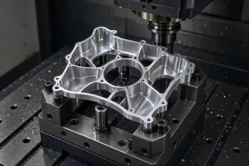
Warping is not usually a sign that the machinist² made a mistake, but rather a sign that internal stresses have been released. When you remove a large volume of material from a metal block, the balance of forces holding that metal in shape disappears.
Prevent warping by selecting pre-stretched materials like 6061-T651, implementing symmetrical machining to balance stress release, and using low-pressure workholding like vacuum fixtures or soft jaws for thin-walled parts to avoid physical deformation during the clamping process.
I once worked with a client who designed a thin shell measuring 100mm x 100mm with only a 2mm wall thickness. After he removed 80% of the material from a solid aluminum block, the part curled up like a Pringle. The internal stress³ from the original rolling process was simply too high for such a thin design. To fix this, I suggested moving to a “balanced” removal approach. We flipped the part multiple times, taking small amounts from each side, and let it rest for four hours between roughing and finishing. This allowed the stress to stabilize naturally.
Clamping force is another silent killer. If you squeeze a thin aluminum part in a vise with too much force, it deforms by maybe 0.05mm. You machine it flat, but when you open the vise, the metal “springs back,” and your flat surface is gone. At Ranglink, we solve this by using custom soft jaws that distribute pressure over a larger area. For extremely fragile parts, we sometimes even use wax to fill the cavities for internal support, which we melt away after machining.
| Strategy | Action Step | Benefit |
|---|---|---|
| Material Choice | Use pre-stretched (T651) plates | Reduces raw material internal stress |
| Process Sequence | Symmetrical material removal | Keeps stress distribution balanced |
| Stress Relief | Natural aging or cryogenic treatment⁴ | Prevents “spring back” after finishing |
| Workholding | Vacuum chucks or soft jaws | Avoids crushing thin-walled structures |
What causes burrs in CNC machining, and how do you remove them?
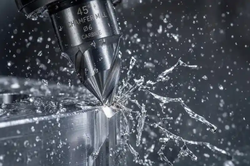
Burrs happen because the material is being “pushed” away instead of being cleanly “cut” by the tool. When a tool gets dull or the feed rate is too slow, the metal acts more like playdough than a solid, resulting in jagged edges.
Burrs are caused by tool bluntness, improper cutting parameters, or high material ductility; they can be removed through manual deburring, vibratory finishing with abrasives, or by programming chamfering operations directly into the CNC cycle to ensure consistency and lower labor costs.
In my workshop, I have a strict rule: for aluminum parts, we swap out tools at 70% of their expected life. Waiting until a tool is completely dull saves a few dollars on hardware but adds hours of expensive manual deburring⁵ labor. Also, many designers think slow feed rates help, but if the tool “rubs” the material rather than “biting” it, it creates a hardened, nasty burr that is very difficult to remove.
The best way to handle burrs is to address them in the drawing. I often ask engineers to specify exactly which edges need a chamfer⁶. Instead of a vague “remove all burrs” note, a note like “C0.3 chamfer on all outer edges” allows us to use a dedicated deburring tool in the machine. This makes the part safer to handle and ensures it won’t cut a technician’s finger or damage a seal during assembly.
Advanced Deburring Methods
- Manual Deburring: Best for low volume or simple outer edges using files or scrapers.
- Vibratory Finishing: Parts are placed in a tub with ceramic or plastic media. This is great for complex internal cavities.
- Electrochemical Deburring: Uses electricity and chemicals to dissolve burrs in hard-to-reach areas like intersecting holes in hydraulic blocks.
How do you eliminate tool marks and chatter for a smooth surface finish?
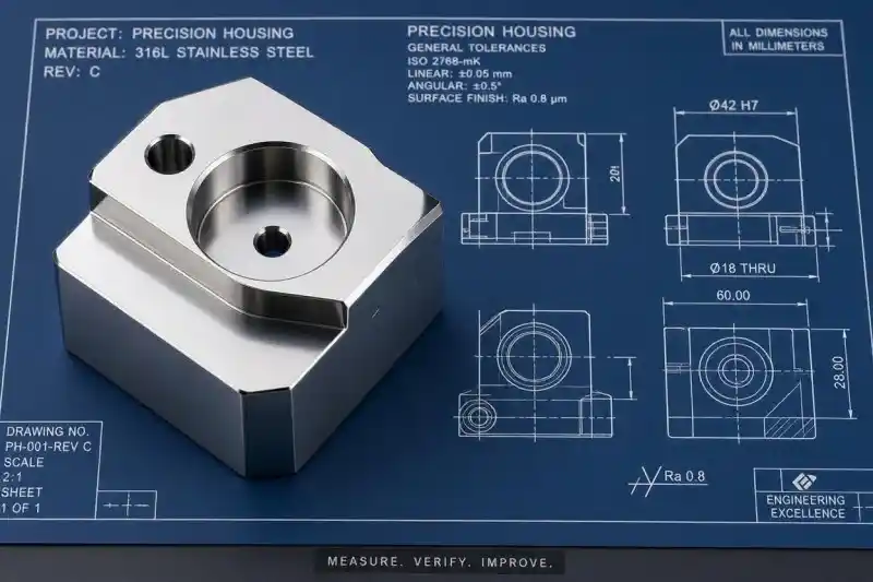
Tool marks and chatter are different “illnesses” that require different treatments. Tool marks are regular patterns left by the tool’s path, while chatter is an irregular vibration that leaves a wavy, “scalloped” finish.
Eliminate tool marks by using high-speed spindles with polished-edge tools and optimize chatter by increasing setup rigidity, shortening tool overhang, and adjusting spindle speeds to avoid the natural resonant frequency of the machine and workpiece combination.
I remember a project for a robotic arm where the client needed a Ra 0.8 surface finish⁷ for aesthetic reasons. Their previous supplier produced a Ra 1.6 finish with visible “waves.” When I analyzed their process, I saw they were using the same tool for roughing and finishing. We switched to a dedicated 3-flute aluminum end mill⁸ with a mirror-polished edge. By shortening the tool overhang from 80mm to 50mm and using a hydraulic holder, we hit a Ra 0.4 finish. The part looked like a mirror without any manual polishing.
The “rigidity chain” is the most important concept here. If the tool is too long, the holder is weak, or the part isn’t clamped tightly, you will get chatter⁹. Sometimes, simply slowing down the spindle¹⁰ by 10% or speeding it up by 10% can move the process away from a “bad” vibration frequency, instantly smoothing out the surface.
| Surface Issue | Primary Cause | Solution |
|---|---|---|
| Regular Tool Marks | High feed rate or dull tool | Reduce feed; use polished finishing tools |
| Random Waves (Chatter) | Lack of rigidity/vibration | Shorten tool overhang; use hydraulic holders |
| Surface “Fuzz” | Heat buildup/low coolant | Increase coolant flow; adjust per-tooth feed |
How can Design for Manufacturing (DFM) reduce CNC defects?
The best way to handle defects is to ensure they never happen in the first place through smart design choices. DFM isn’t just a final check; it is a way to make your design “machining-friendly” from the start.
Design for Manufacturing (DFM) reduces defects by standardizing wall thicknesses to prevent warping, adding internal radii to prevent tool breakage, and widening tolerances on non-critical dimensions to allow for more stable, predictable machining processes.
When I review drawings at Ranglink, I look for “stress points.” If a part has a 5mm wall connected to a 1mm wall, it will warp during cooling or machining. I often suggest making the walls more uniform. Another common issue is sharp internal corners. A sharp corner forces the CNC tool to stop and turn abruptly, which causes “dwell marks” and increases the risk of the tool snapping. By adding a small radius¹¹ (like R2), the tool can move in a smooth, continuous motion, resulting in a much cleaner finish.
Effective DFM¹² is about communication. I always provide a “DFM Remark” with my quotes. If I see a deep hole that will be hard to clear of chips, I suggest making it a through-hole. If I see a ±0.02mm tolerance¹³ on a plastic cover, I suggest loosening it to ±0.1mm. These small changes don’t hurt the function of the part, but they drastically reduce the chance of a defect and lower the price for the customer.
Key DFM Focus Areas
- Wall Thickness: Keep it uniform to avoid uneven cooling and warping.
- Internal Radii: Always avoid sharp internal 90-degree corners; use the largest radius possible.
- Tolerance Layering: Reserve tight tolerances for functional mating surfaces only.
- Hole Depth: Avoid holes deeper than 5x the diameter to prevent tool deflection and breakage.
Conclusion
Preventing CNC defects requires choosing stable materials, ensuring setup rigidity, and using DFM to simplify the geometry. By collaborating early with Ranglink, you turn complex blueprints into perfect reality.
Ready to start your next project?
Whether you need high-precision batch production or expert advice on the best machining path, I am here to help.
Contact me today for a fast quote:
Email: info@ranglink.com
WhatsApp: Message us on WhatsApp
- Overview of 3D modeling and its role in mechanical engineering.
- Details about the machinist profession and precision metalworking.
- Explanation of residual and internal stresses in manufactured parts.
- Overview of cryogenic treatments used to relieve stress in metals.
- Engineering definition of burrs and the deburring process.
- Explanation of chamfers and their use in mechanical design.
- Scientific standards and definitions for measuring surface roughness.
- Technical guide to end mills and their uses in CNC machining.
- Overview of machining vibrations and chatter during metal cutting.
- Information on spindles, the rotating axis of a machine tool.
- Engineering principle of using a radius or fillet to reduce stress.
- Principles of Design for Manufacturability (DFM) in product engineering.
- Guide to engineering tolerances and precision manufacturing limits.