
Design errors often lead to expensive scrap and missed deadlines. When your factory says a part is “unmanufacturable,” the issue is usually how the tolerances are defined on your drawing. A solid understanding of GD&T in CNC machining can prevent this.
GD&T (Geometric Dimensioning and Tolerancing) is a symbolic language used on engineering drawings to define the allowable deviation of feature geometry. It moves beyond simple plus/minus dimensions to ensure parts fit and function correctly while often reducing manufacturing costs through a more scientific approach to tolerances.
I have seen many engineers struggle when their perfect 3D models¹ turn into failed physical prototypes. You might feel that your supplier is being difficult, but often, the breakdown happens in the “translation” of your design intent. This is why understanding GD&T is not just a technical skill; it is a cost-saving strategy that bridges the gap between your workstation and our shop floor at Ranglink.
What is GD&T and why is it important in CNC machining?
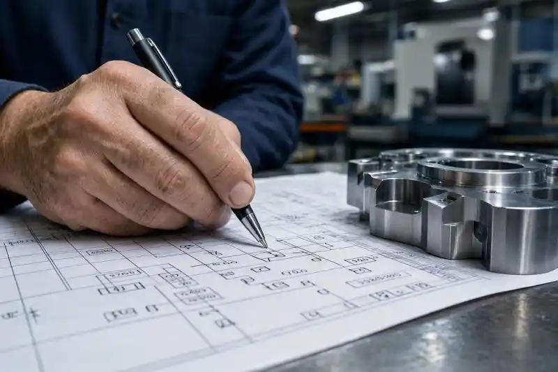
Traditional dimensioning often creates a “tolerance stack-up²” that makes assembly impossible even when every part is within spec. You might spend hours tightening tolerances to fix this, but that only drives up your costs.
GD&T is a “smarter” tolerance system, not a “tighter” one, that acts as a translator for design intent. It uses datums and tolerance zones to tell the machinist exactly how a part functions, allowing for wider tolerances on non-critical areas while ensuring perfect fit for assembly.
I once reviewed a customer drawing where every single dimension had a strict ±0.02mm tolerance. The part was incredibly hard to make, and the price was high. After we sat down and converted it to GD&T, we realized only two holes were critical for the assembly. We applied a position tolerance to those and loosened everything else to ±0.1mm. The result? We cut the machining time by 30%, and the part worked perfectly.
The Real Power of Datums
In a real-world case at Ranglink, we produced mounting plates for an automated line. The customer used standard ±0.05mm tolerances for all hole positions. Every part passed inspection, but the bolts wouldn’t line up during assembly. The problem was that the three different reference edges used for measurement had their own errors that added up. GD&T solves this by establishing a Datum Reference Frame³ (DRF). This forces the machinist to use the same starting point for every feature, eliminating cumulative error.
Why Your Supplier Needs to Speak GD&T
| Capability | Without GD&T | With GD&T (Ranglink Approach) |
|---|---|---|
| Assembly Success | High risk of “hidden” interference | Parts guaranteed to fit via functional zones |
| Cost Control | Tighter tolerances = Higher scrap | Optimized tolerances = Lower cost |
| Inspection | Ambiguous measurement points | Clear, repeatable measurement via Datums |
If a supplier only looks at plus/minus values and ignores symbols like position or runout, they are guessing. At Ranglink, I personally circle every GD&T symbol during the quote stage. If the datums are confusing, I suggest changes before we even start. This prevents 100% of the “it fits on screen but not in hand” problems.
What is the difference between standard (plus/minus) tolerances and GD&T?
Many designers think plus/minus is simpler, but it actually limits the “bonus” space available for a part to be acceptable. It creates a square boundary that doesn’t match how parts actually move or fit.
Plus/minus tolerance creates a rectangular “box” zone, while GD&T (Position) creates a circular zone. This circular zone provides about 57% more usable tolerance area for the same functional requirement, allowing the factory more room to work without sacrificing the quality of the final assembly.
A standard ±0.1mm tolerance on X and Y creates a square. If a hole is slightly off in the corner of that square, it might be 0.14mm away from the center, which might fail a standard check but still work in assembly. GD&T recognizes this. Furthermore, standard tolerances cannot control the shape of a part. I have seen shafts that met the diameter spec but were oval-shaped or slightly curved. They wouldn’t fit into a bearing. GD&T symbols like Circularity⁴ and Cylindricity fix this by controlling the form, not just the size.
Geometric Control vs. Linear Measurement
Standard dimensioning lacks a “legal” baseline. If you don’t define a datum, two different inspectors might measure from two different sides, getting two different results. This causes endless arguments between engineers and shops. GD&T uses Datums A, B, and C as the “law.” It defines exactly where to measure from.
When to Use Each Method
| Feature Type | Best Tolerance Method | Reason |
|---|---|---|
| Simple Plates / Brackets | Plus/Minus (±) | Lower complexity and inspection cost. |
| Mating Holes / Patterns | GD&T (Position) | Ensures alignment and uses bonus tolerance. |
| High-Speed Rotating Shafts | GD&T (Runout) | Prevents vibration and mechanical wear. |
| Complex Curved Surfaces | GD&T (Profile) | Only way to accurately define 3D shapes. |
I always tell my engineering clients: don’t use GD&T for everything. Use it for mating surfaces and functional features. Using it for a non-critical outer chamfer just wastes money. Keeping it simple where possible is the most economical way to design.
What are the most common GD&T symbols and how do you read them?
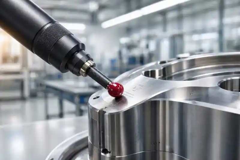
Reading a feature control frame can feel like deciphering code. However, once you understand the logic behind Position, Profile, and Runout, you can design parts that are much easier to manufacture.
Common symbols include Position (⌖), which controls where a feature is; Profile (⌒), which controls the entire shape of a surface; and Runout (↗), which ensures a part is concentric. Reading them requires looking at the tolerance value, the Material Condition (like MMC), and the Datum references.
Position is the most frequent symbol I see at Ranglink. It often includes the “M” symbol, meaning Maximum Material Condition (MMC). This is a game-changer. It means if a hole is drilled slightly larger, the position tolerance can actually increase. Most machinists don’t realize this link. If they did, they would realize that a slightly “out of place” hole might still be perfectly fine if the hole itself is on the larger side of the spec.
Deep Dive into Specific Symbols
- Position (⌖): Used for holes and tabs. It tells us where the center should be. If you see the “M” symbol, we can use functional gauges (pins) to check parts quickly, saving you money on inspection.
- Profile of a Surface (⌒): This is the hardest to meet. It controls the “cloud” around a 3D surface. We use this for robot arms or turbine blades. It requires CMM (Coordinate Measuring Machine⁵) scanning, which costs 5 to 10 times more than basic tools.
- Runout (↗): Critical for anything that spins. I use V-blocks and dial indicators⁶ to check this. If the runout is bad, your motor or gearbox will vibrate and fail.
The Importance of Datum Order
The order of A, B, and C matters. “A” is the primary surface that sits on the machine table. “B” is the secondary stop, and “C” is the third. If a machinist sets up a part using Datum B as the primary because it is easier to clamp, the measurements will be wrong. I once saw a batch of parts fail CMM inspection because the inspector used the wrong datum sequence, even though the parts were actually perfect. At Ranglink, we verify the setup against the DRF before the first chip is even cut.
How does GD&T impact your CNC machining costs?
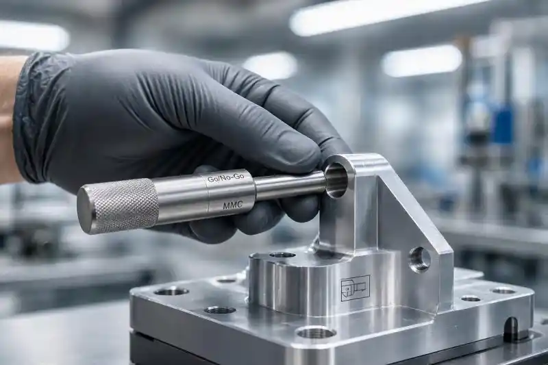
If used correctly, GD&T is a cost-reduction tool. If used poorly, it can double your price. The key is knowing which features truly drive the function of your product and focusing your “budget” there.
GD&T reduces costs by allowing wider manufacturing tolerances through “bonus” zones and by simplifying the inspection process with functional gauges. However, over-specifying with too many symbols or choosing difficult datums can significantly increase setup time and inspection labor costs.
The biggest mistake I see is “safety labeling.” An engineer might put Position, Profile, and Runout on the same feature just to be “safe.” This forces the shop to perform three different, expensive inspections. At Ranglink, I often provide DFM (Design for Manufacturing⁷) feedback suggesting that the customer choose the flat bottom of the part—the surface that naturally touches the machine—as Datum A. This makes machining and inspection faster and cheaper.
Cost Factors in GD&T
| GD&T Element | Cost Impact | Recommendation |
|---|---|---|
| MMC (M) Modifier | Lower | Allows the use of cheap “Go/No-Go” gauges instead of slow CMM. |
| Complex Datums | Higher | Avoid using curved or hard-to-reach surfaces as primary datums. |
| Tight Profile Specs | Very High | Use only for critical aerodynamic or aesthetic surfaces. |
I remember a project where we quoted $120 per part for a standard ±0.05mm drawing. We worked with the engineer to switch to GD&T, focusing only on the critical mating holes. We loosened the non-critical edges to ±0.2mm. The price dropped to $65. We didn’t change the design; we just changed how we measured it. By using MMC, we were also able to use a custom gauge that checked parts in 30 seconds rather than 5 minutes on a CMM. This is how smart design turns into real-world savings.
Conclusion
GD&T ensures your complex designs work the first time by focusing on functionality. By using datums correctly and applying MMC, you can lower machining costs and avoid assembly failures.
Ready to start your next project?
Whether you need high-precision batch production or expert advice on the best machining path, I am here to help.
Contact me today for a fast quote:
Email: info@ranglink.com
WhatsApp: Message us on WhatsApp
- Overview of 3D modeling and computer-aided design in engineering.
- Explanation of tolerance stack-up and dimensional analysis.
- Engineering definition of a datum and Datum Reference Frame.
- Guide to Geometric Dimensioning and Tolerancing (GD&T) symbols and rules.
- Information on Coordinate Measuring Machines (CMM) for precision inspection.
- Technical details on dial indicators used for measuring runout and alignments.
- Principles of Design for Manufacturing (DFM) in product engineering.