
Do high manufacturing quotes keep stalling your projects and blowing your budget? You can slash these costs by making smart design choices before the first chip is even cut.
You can reduce CNC machining costs by simplifying part geometry, relaxing non-critical tolerances, and choosing materials that are easier to machine. By focusing on Design for Manufacturing (DFM) principles, you minimize setups and specialized tooling, which directly lowers the price per part without sacrificing functional performance.
I have spent over 20 years at Ranglink looking at thousands of blueprints, and I see the same story every day. An engineer sends over a design that looks beautiful on a screen, but the price tag makes them jump. They think the material or the shop’s labor rate is the problem, but usually, it is the design itself. I want to help you understand that the power to lower the price is in your hands. If you stay with me, I will show you exactly how we look at your drawings and where the “hidden money” is buried in your CAD¹ models.
What makes CNC machining so expensive?
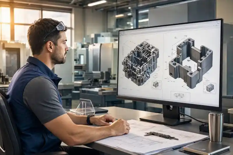
Are you tired of paying premium prices for parts that seem simple to design? Many factors drive up costs, but you can only control three: geometry complexity, tolerance levels, and the number of setups.
CNC machining is expensive because of machine runtime, specialized labor, and the overhead of multiple setups. High costs often come from “over-designing”—adding tight tolerances or complex features that do not improve function but require slower machining speeds, more expensive tools, and constant manual intervention by skilled technicians.
When I review drawings at Ranglink, I always ask: “Is this feature a must-have, or just a nice-to-have?” Often, 20% to 30% of the machining work is actually unnecessary. People think a high price means quality, but usually, it just means you paid for precision you didn’t need. I once saw an aluminum housing where every surface was marked with a Ra 0.8 surface finish². In reality, only the top face was visible; the other five were hidden inside the machine. By relaxing those internal faces to Ra 3.2, we dropped the price by 40%.
The biggest “hidden” cost is the number of setups. If a part needs features on five sides, that means five setups. Each setup takes time to align and secure. If you can redesign the part so all features are reachable from just two sides, you cut that setup time by 60%. I once had a client with a bracket that required four setups and cost $180. We suggested moving the side mounting ears to the front. The part worked exactly the same, but it only needed one setup. The price dropped to $95—a 47% saving just by changing the orientation.
The Breakdown of Machining Cost Drivers
| Cost Category | Driver | Impact on Quote | DFM Solution |
|---|---|---|---|
| Setup Time | Number of orientations | High (Manual labor) | Consolidate features to 1 or 2 sides |
| Machining Time | Feed rates³ & tool paths | Medium | Use larger internal radii for faster cutting |
| Tooling | Custom or small tools | Medium | Standardize hole sizes and corner radii |
| Quality Control | Inspection requirements | Variable | Minimize tight tolerances to avoid CMM use |
《Why Is CNC Machining Expensive》→ “For a deeper look at the cost drivers behind a CNC quote, read our full breakdown here.”
How can optimizing part geometry reduce CNC machining costs?
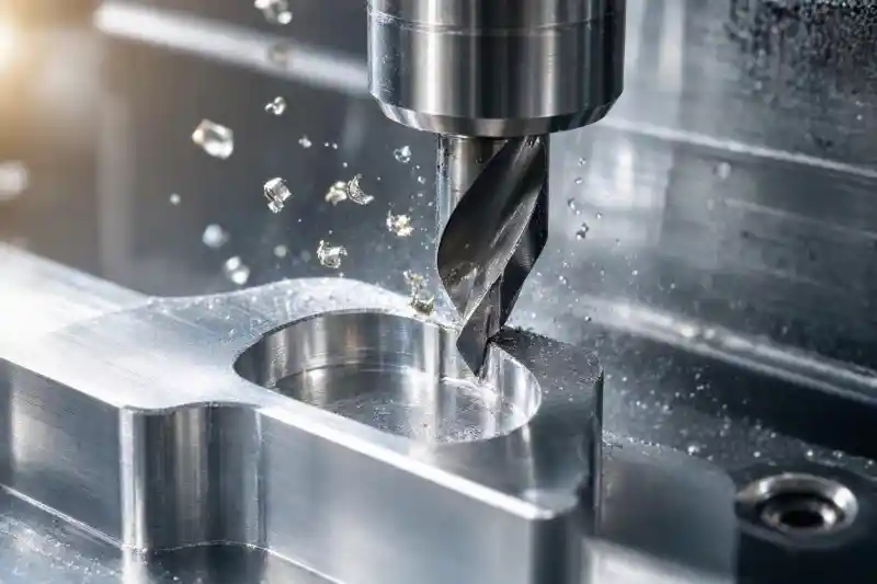
Does your design require special tools or slow machining speeds just to reach a single hole? Complex geometry can double your costs if the cutting tool cannot easily “reach” the features you have drawn.
Optimizing geometry reduces costs by allowing the use of standard tools and maintaining high cutting speeds. By avoiding deep cavities, using consistent wall thicknesses, and adding internal radii, you ensure the machine can run efficiently with less risk of tool breakage or part deformation during the process.
The first rule of geometry is: make sure the tool can reach it. I often see designs with a side hole buried deep inside a cavity. A standard mill can’t get in there, so we have to use expensive EDM⁴ or an angle head. If you move that hole to an open face, the cost drops instantly. I also recommend keeping wall thicknesses consistent. If one wall is 5mm and the next is 1mm, the part will warp because of heat. We once thickened a wall from 1mm to 1.5mm. It added $3 in material but saved $12 per part because the scrap rate⁵ dropped from 15% to 2%.
Internal corners are another “money-saver.” Sharp corners force the tool to stop and turn, which is slow and breaks tools. If you use a radius⁶, the tool flows smoothly at high speeds. I suggest a minimum R2 for aluminum and R1 for steel. If you absolutely need a sharp corner for assembly, ask for a “dog-bone” undercut or a relief hole. This lets the mating part fit without forcing the mill to do the impossible. We recently helped a customer with a robot housing. By moving an internal oil hole so it could be drilled from the top instead of the side, we saved them $100 per unit.
Geometry Optimization Strategies
- Standardize Radii: Use the same radius for all internal corners so the shop doesn’t have to change tools.
- Limit Cavity Depth: Try to keep the depth-to-width ratio of a cavity below 4:1. Deep pockets require long tools that vibrate and leave poor finishes.
- Avoid Thin Walls: Keep aluminum walls above 0.8mm and steel above 1.0mm to prevent vibration and “chatter⁷” marks.
- Simplify Holes: Use standard drill sizes and avoid holes that are deeper than 5 times their diameter.
Do tight tolerances really increase your machining quote?
Do you mark every dimension with a tight tolerance “just to be safe”? This habit is one of the fastest ways to turn a $50 part into a $200 part without adding any real value.
Yes, tight tolerances increase costs exponentially because they require slower feeds, specialized fixtures, and frequent tool changes. As you move from ±0.1mm to ±0.01mm, the price can triple because the machinist must spend more time measuring and adjusting the machine to hit those numbers consistently.
In my experience, 80% of dimensions on a drawing do not need tight tolerances⁸. I see aluminum plates where the outer shape is marked ±0.02mm, but it’s just a heat sink⁹ that sits in open air. If you relax that to ±0.5mm, the machine can fly through the cut. Only the mounting holes actually need precision. I once had a client with an automation plate where every single hole was ±0.02mm. After talking to him, we found only the bearing holes mattered. By relaxing the weight-reduction holes to ±0.5mm, the price dropped from $160 to $85.
There is also a hidden cost: inspection. If you ask for ±0.005mm, I can’t use a caliper. I have to use a CMM¹⁰ (Coordinate Measuring Machine). Measuring one part can take 10 minutes, and for large batches, the inspection fee might be higher than the machining fee. If you relax it to ±0.05mm, we use a micrometer or a go/no-go gauge in 30 seconds. I always tell my friends in design: put your “tolerance budget” where the parts actually touch. If it’s just for “looking good,” keep it loose.
Tolerance vs. Cost Impact
| Tolerance Range | Cost Impact | Tooling/Method |
|---|---|---|
| ±0.5 mm | Baseline | Standard Machining (Fast) |
| ±0.1 mm | +20% | Standard Machining (Normal) |
| ±0.02 mm | +100% | High-Precision Setup / Slow Feed |
| ±0.005 mm | +300% or more | Grinding¹¹ / Lapping / CMM Inspection |
《CNC Machining Cost Breakdown》→ “For a detailed tolerance-to-cost multiplier table, see our cost breakdown guide.”
Which materials and surface finishes offer the best cost savings?
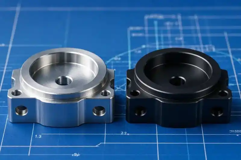
Are you choosing materials based on the lowest price per pound, or the lowest price to machine? Sometimes the “cheaper” raw material ends up costing you more because it is difficult and slow to cut.
The best cost savings come from selecting materials with high machinability, like Aluminum 6061 or Stainless 303, and choosing “As-Machined” finishes for internal parts. Avoiding rare alloys and complex surface treatments like custom-color anodizing or mirror polishing can reduce your total part cost by more than 50%.
Think of it this way: Stainless 303¹² costs about 5% more than 304, but it machines 30% faster and tools last twice as long. In the end, the 303 part is 18% cheaper. The same goes for Aluminum. 6061¹³ is the “workhorse” for a reason—it’s easy to cut and cheap. Unless you are building an airplane wing, you probably don’t need the extra strength of 7075¹⁴, which is much more expensive and harder on tools. I always suggest starting with the most common material that fits your needs.
Surface finishing also hides traps. If a part is inside a box, “As-Machined” is perfect. You don’t need to pay for bead blasting or anodizing¹⁵. Also, remember that colors matter. Black and silver are standard at most shops. If you want a custom red or green, I have to change the chemical tanks, which adds a “setup fee.” We once had a customer who wanted 7075 aluminum with a mirror polish and clear anodizing for an outdoor shell. It was $280. We suggested 6061 with a bead blast and black hard anodizing. It looked great, lasted longer in the sun, and cost only $95. That’s a 66% saving just by matching the finish to the actual environment.
Material & Finish Comparison for Savings
- Aluminum 6061 vs. 7075: Choose 6061 for most structural parts to save on material and machining time.
- Stainless 303 vs. 304: Use 303 for machined parts unless welding is required; it’s much more “tool-friendly.”
- As-Machined Finish: Best for non-visible internal parts. Zero extra cost.
- Bead Blast + Anodize: Best for “pro” looks. Use standard black or silver to avoid extra tank charges.
- Masking Costs: If you need a tight tolerance on an anodized part, try to design it as a raised “boss.” This avoids the manual labor cost of applying tape or plugs during the plating process.
Conclusion
Smart DFM means choosing the right geometry, tolerances, and materials to balance function and cost. By simplifying your designs, you help shops like Ranglink deliver high-quality parts faster and cheaper.
Ready to start your next project?
Whether you need high-precision batch production or expert advice on the best machining path, I am here to help.
Contact me today for a fast quote:
Email: info@ranglink.com
WhatsApp: Message us on WhatsApp
- Overview of Computer-Aided Design (CAD) and its role in engineering.
- Scientific standards and definitions for measuring surface roughness.
- Guide to calculating cutting speeds and feed rates for CNC machines.
- Explanation of Electrical Discharge Machining (EDM) used for complex cuts.
- Industrial definition of scrap and manufacturing waste material.
- Engineering principle of using a radius or fillet to reduce stress.
- Overview of machining vibrations and chatter during metal cutting.
- Guide to engineering tolerances and precision in manufacturing.
- Information on heat sinks and thermal management in electronics.
- Overview of Coordinate Measuring Machines (CMM) for precision inspection.
- Explanation of precision grinding for fine material removal.
- Material data and specifications for 304 and 303 stainless steel.
- Properties and common industrial applications of 6061 aluminum alloy.
- Technical specifications of high-strength 7075 aluminum alloy.
- Technical explanation of the anodizing surface treatment process.