
In the precise world of industrial robotics, the flawless motion of a robotic arm is a symphony orchestrated by its control system but performed by its mechanical body. The ultimate Robotic Precision CNC Machining can deliver defines the limits of a robot’s accuracy and repeatability. While software and sensors guide the path, it is the physical execution—dictated by the dimensional perfection of gears, housings, and arm links—that determines real-world performance. This article delves into how scientific tolerance allocation and specialized CNC machining strategies converge to manufacture the critical structural components that form the backbone of reliable, high-precision robotics.
Contact
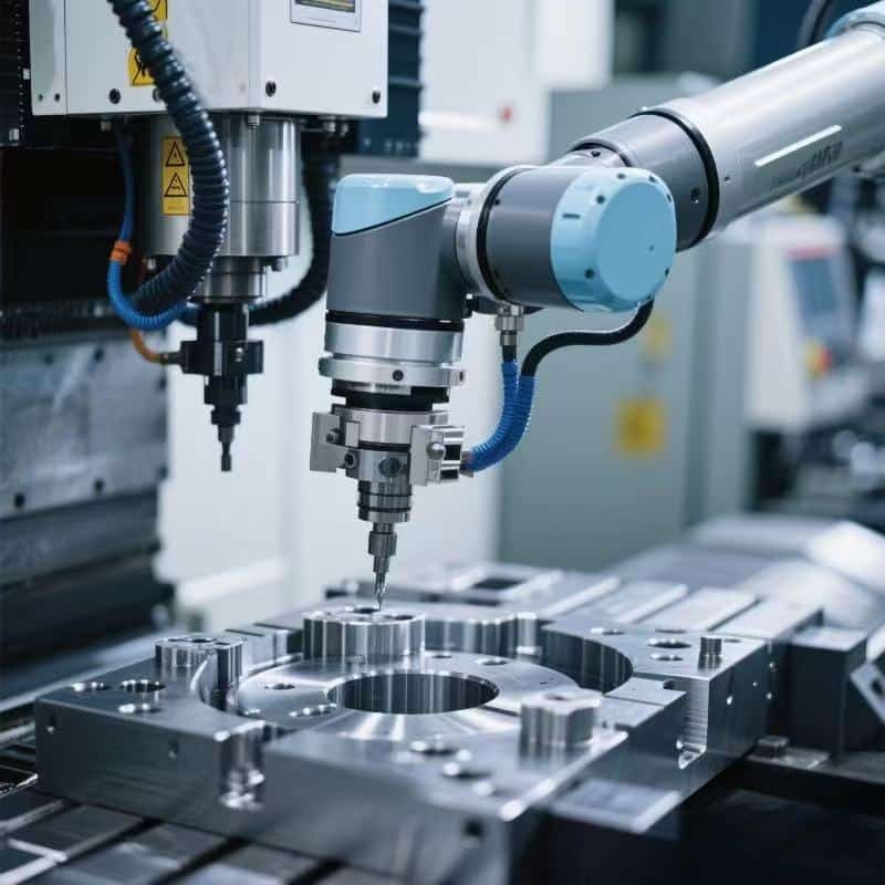
Figure 1: The end result of precision manufacturing: a robotic arm’s smooth operation relies entirely on the micron-level accuracy of its CNC-machined structural parts. (Source: Unsplash)
1. The Critical Link: Tolerance Allocation in Design for CNC Manufacturability
Before a single tool path is generated, precision begins on the drawing board. Tolerance allocation is the strategic distribution of permissible dimensional variation across all parts in an assembly to meet a final system-level accuracy goal cost-effectively.
For robotic arms, this is a complex kinematic chain problem. An error in a base housing bearing bore magnifies at the end-of-arm tooling. Effective allocation for CNC production follows these principles:
- Functional Criticality: Identify mating surfaces, bearing seats (often requiring IT6-IT7 tolerances), and gear interfaces as “critical features.” Non-functional surfaces can have relaxed tolerances (IT9-IT10) to reduce machining cost.
- Process-Oriented Limits: Allocate tolerances that align with standard CNC capabilities. Specifying ±0.002mm on a large, thin-walled part may be unstable or prohibitively expensive. Collaboration with your CNC partner during design is key.
- Statistical Stack-Up Analysis: Using methods like Root Sum Square (RSS) rather than simple Worst-Case analysis allows for tighter system precision without over-constraining every component, as detailed in guides by the American Society of Mechanical Engineers (ASME).
A well-allocated tolerance drawing is a blueprint for efficient, high-yield CNC production.
2. CNC Machining Strategies for Core Robotic Components
Turning a design into a precise physical part requires tailored CNC strategies. Here, we focus on three critical component categories.
2.1 Robotic Arm Links: Combating Deflection for Long-Range Accuracy
Challenge: Long, slender aluminum links are prone to deflection during machining and under load, compromising straightness and parallelism.
CNC Machining Strategy:
- Strategic Fixturing & Sequencing: Use custom fixtures that support the link along its entire length. Employ a “rough, stress-relieve, finish” sequence: rough machine to near-net shape, unclamp for stress relief, then re-fixture for final finishing to stable geometry.
- Adaptive Machining & Probe Integration: Utilize on-machine touch probes to map the part’s datum surfaces after initial clamping. The CNC program can then adapt tool paths to compensate for any residual warp or fixture imperfection, a technique supported by advanced CNC controllers from manufacturers like Siemens.
Contact
Figure 2: CNC machining of a long robotic arm link, requiring specialized fixturing and toolpath strategies to maintain geometric integrity. (Source: Unsplash)
2.2 Joint Housings and Gearbox Casings: Precision of Internal Geometries
Challenge: These parts feature complex internal networks of precise bearing bores and gear meshing surfaces that must maintain true position, perpendicularity, and coaxiality within microns.
CNC Machining Strategy:
- Single-Setup Machining (5-Axis): The gold standard is to complete all critical internal and external features in one clamping on a 5-axis CNC mill. This eliminates cumulative errors from repositioning between multiple setups.
- Bore Finishing Techniques: After precision boring, employ skiving, roller burnishing, or honing as a final operation. These processes achieve superior surface finish (Ra < 0.4 µm) and perfect roundness, critical for bearing life and minimal runout. The Precision Machined Parts Association (PMPA) offers extensive resources on these finishing methods.
2.3 Base Frames and Mounting Plates: The Foundation of Stability
Challenge: The base must be an immovable foundation. Any distortion here propagates through the entire robot structure.
CNC Machining Strategy:
- Planarity through Fly Cutting: For large surface plates, a large-diameter fly cutter on a rigid CNC boring mill provides the best path to achieve overall flatness over a wide area.
- Stress-Relieving Intermediates: For cast iron or steel bases, incorporate a vibration or thermal stress-relieving cycle between roughing and semi-finishing operations to ensure long-term dimensional stability.
3. The Supporting Role of Material Science and Metrology
Material Selection for Machinability and Stability: The choice of material is integral to the CNC process.
- Aluminum 7075-T6: An excellent choice for moving arms due to its high strength-to-weight ratio and good machinability. It allows for higher feed rates and a good surface finish.
- Ductile Iron (e.g., Grade 65-45-12): Often used for bases and heavy joint housings. Its graphite microstructure provides superior damping properties, absorbing vibration for better precision. Its machining requires different tool geometries and coatings, such as those specified by tooling experts like Sandvik Coromant.
In-Process and Post-Process Metrology: Precision must be measured to be guaranteed. Integrating Coordinate Measuring Machine (CMM) verification with CNC machining data ensures components meet the tightest tolerances. Statistical Process Control (SPC) charts for key dimensions provide real-time assurance of machining consistency.
Conclusion: A Synergistic Partnership for Peak Performance
Achieving the robotic precision demanded by modern automation is not a sequential process but a deeply integrated one. It requires a continuous dialogue between the robotics designer’s vision and the CNC machining engineer’s expertise—from the initial tolerance stack-up analysis to the final quality validation.
At RangLink, we specialize in this synergy. Our engineering team partners with you to perform Design for Manufacturability (DFM) reviews, optimizing designs for robust and cost-effective CNC production. Our shop floor is equipped with advanced 5-axis CNC centers and in-process metrology to execute these strategies, turning precise designs into reliable, high-performance robotic components.
Ready to build precision into your next robotics project? Contact RangLink today for a free, no-obligation DFM review and quotation. Submit your component drawings, and let’s discuss how our Robotic Precision CNC Machining capabilities can bring your designs to life with unmatched accuracy.
📩 Email: rang@ranglink.com
📱 WhatsApp: +86 17338532394
🌐 Request a quote: www.ranglink.com